
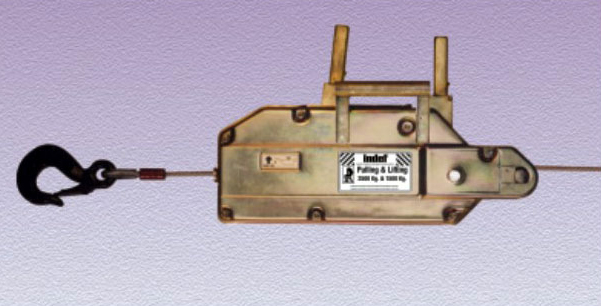
Pulling & Lifting Machine
We provide a comprehensive range of Pulling & Lifting Machines that is used in various industries such as automobile industries, construction industry and textile industry. These are suitable of all sorts of operations including pulling, lifting and lowering. Our range of pulling and lifting machines is widely appreciated for its attributes such as portability, rugged construction, operational efficiency and efficacy to tackle heavy loads. These can also be customized as per the application requirements of our clients.
 Manufactured in ISO 9001 : 2008 certified company
Assured quality and interchangeability of parts
Rugged and light weight steel body
Assured reliability in difficult conditions, easier to handle
Anti-corrosive powder coated, zinc passivated parts
Anti rust & better aesthetics
Alloy steel heat treated jaws
Long life, prevents slipping
Shear pin in forward/lifting lever
Prevents over loading, safety ensured
Ergonomically designed lever
Ease of operation
Specifications/Dimensions
| Specification | Unit | Model | |||
| PL-1 | PL-2 | PL-3 | |||
| Normal capacity | Lifting | MT | 0.8 | 1.6 | 3.2 |
| Pulling | MT | 1.25 | 2.5 | 5.0 | |
| Wire rope diameter | Inch | 0.3 | 0.4 | 0.6 | |
| Rope breaking load | Kg | 4000 | 8000 | 16000 | |
| Length of telescopic operating handle |
Inch | 25.6 | 24.4/41.0 | 24.4 / 41.0 | |
| Effort on operating handle | Kg | 30-45 | 40-65 | 50-80 | |
| Overall dimensions (L x W x H) | Inch | 17.3x3.9x 11.0 | 22.0x5.1 x 14.2 | 27.6 X 5.9 x 15.8 | |
| Weight of unit | Kg | 7.5 | 15 | 30 | |
| Wire rope weight per 3 ft. | Kg | 0.27 | 0.51 | 1 | |
NOTE :
1) In general manufactured as per IS 5604 -1984.
2) Any length of wire rope is available.
3) Nominal capacity can be increased by use of multiple sheave blocks (by increasing number of rope falls).
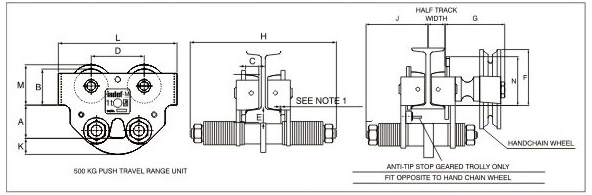
Push-Pull Geared Travelling Trolley
 Available in push or hand geared travel.
Anti drop and de-railing guide
Precision-machine runners mounted on sealed ball bearings.
Available in three basic range with further adjustment of flange width.
Anti-corrosive powder coated finish.
DIMENSIONS, WEIGHTS AND PERFORMANCE DATA (mm)
| Push | Push Geared | Geared | Geared | ||||||
| Capacity MT | 0.5 | 1 | 3 | 5 | 10 | ||||
| Inside of Wheel flanges mm | Range 1 | 50-130 | S8-1M) | 90-160 | 110-150 | 140 I80 | |||
| Range 2 | 140-200 | 150-210 | ! 60-220 | 160-210 | 190? 10 | ||||
| Range 3 | 210-305 | 210-305 | 220-305 | 215-265 | 215-245 | ||||
| A Seat of susp. plate 10 runner tread/Beam Bottom | Range 1 & 2 mm | 75 | 89 | 1 10 | 84 | 137 | |||
| Range 3 mm | 115 | 129 | 155 | ||||||
| B Runner : tread diameter | 50 | 65 | 90 | 175 | 225 | ||||
| C Runner tread width mm | 20 | 25 | 30 | 45 | 50 | ||||
| D Runner centers | (push) min | 70 | 90 | 125 | - | • | |||
| (geared) mm | - | 123 | 157 | 253 | 313 | ||||
| E Underside of runner to suspension plate | 18 | 28 | 28 | - | - | ||||
| F Underside of runners to top of hand chain wheel geared travel only mm | 101 | 106 | 123 | - | - | ||||
| G Beam flange to shaft end | mm | - | 124 | 124 | 180 | 275 | |||
| H Overall width, push travel only | Range 1 mm | 210 | 248 | 27-3 | - | - | |||
| Range 2 mm | 320 | 320 | 340 | ||||||
| Range 3 mm | 410 | 410 | 425 | ||||||
| J Cross bolt to track centreline on ungeared side (geared trolleys only) | Range 1 | track widths J mm |
- | 58-100 132 |
100-126 lb? |
170 | 210 | ||
| track widths J mm |
- | 100 -140 120 |
126 153 134 |
||||||
| Range 2 | track widths J mm |
- | 140-166 164 |
153-192 184 |
200 | 225 | |||
| track widths J mm |
- | 166-210 152 |
192-216 166 |
||||||
| Range 3 | track widths J mm |
- | 210-263 238 |
216-263 2C5 |
225 | 240 | |||
| track widths J mm |
- | 263-305 205 |
263-305 213 |
||||||
| K Depth of plate Range 1. 2 S 3 mm | 21 | 21 | 34 | - | - | ||||
| L Overall length | (push) mm | 160 | 200 | 275 | - | - | |||
| (geared) min | - | 238 | 350 | 550 | 690 | ||||
| M Underside to runner to flange push mm | 60 | 75 | 105 | - | - | ||||
| N Underside of runner lo gear tip (geared) mm | - | 90 | 115 | - | - | ||||
| Minimum radius of track curve mm | (push) | 1250 | 2000 | 2500 | |||||
| (geared) | 2000 | 2500 | 2600 | 3200 | |||||
| Push travel weight in Kg |
Range 1 | A 0 | 10.5 | 18.5 | |||||
| Range 2 | 4.5 | 11.0 | 20.0 | ||||||
| Range 3 | 6.5 | 14 5 | 25.5 | ||||||
| Geared travel weight tn Kg |
Range 1 | - | 11.5 | 20.0 | 70 | 151 | |||
| Range 2 | - | 12.5 | 21.5 | 72 | 153 | ||||
| Range 3 | - | 16.0 | 27.0 | 75 | 155 | ||||
1. Nominal 1.5 mm clearance to be allowed from edge of track flange to inside of wheel flange (3mm overall on both side)
2. Overall width of geared travel trolleys = J + (1/2 x track width) + G. On 500 to 2500 Kg. units when using the narrower track widths the cross bolt adjusting washers are to be assembled such that the end of the cross bolt is clear of the hand chain wheel.
3. Weight of trolleys only exclude hand chain. Hand chain is 0.45kg/m per linear length.
4. Bottom of hand chain loop is 800 mm from ground level.
5. Pusher bar fixing holes provided upto 3T models.
6. Anti-tip stop fitted to all hand geared versions upto 3T models.
7. Buffers available as an option.
Ratchet Lever Hoist Link Chain Type
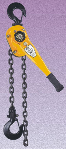
Use of link chain
Allows more flexibility
Superior asbestos free brake
For safe operation
Low operating effort
Less fatigue to operator
Robust steel construction
Sturdy design
Light weight and compact
Ease of handling
Grade 100 load chain
Longer life & high safety
Anti corrosive powder coated finish
Better aesthetics
Safety latch on hooks
Safe operation
Ergonomically design lever
Ease of operation
SPECIFICATIONS / DIMENSIONS (mm)
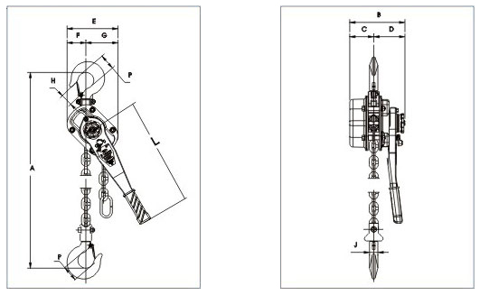
| CAPACITY | 750 kg. | 1.5 1 | 3 T. | 6T. |
| NUMBER OF FALLS | 1 | 1 | 1 | 2 |
| DIMENSIONS (mm) | ||||
| A* MINIMUM HEADROOM | 275 | 345 | 420 | 570 |
| A' MAXIMUM FOR STD. LIFT | 1500 | 1500 | 1500 | 1500 |
| B | 150 | 163 | 200 | 200 |
| C | 53 | 63 | 90 | 90 |
| D | 97 | 100 | 110 | 110 |
| E | 126 | 148 | 189 | 247 |
| F | 41 | 47 | 55 | 72 |
| G | 85 | 101 | 134 | 175 |
| H | 31 | 37 | 44 | 51 |
| P | 40 | 50 | 52 | 68 |
| J | 18 | 2b | 28 | 36 |
| L | 290 | 405 | 405 | 405 |
| LIFT (STD. CHAIN)(m)+ | 1.5 | 1.5 | 1.5 | 1.5 |
| EFFORT TO RAISE FULL SWLkg. | 22 | 32 | 39 | 44 |
| WEIGHT kg. STD. CHAIN | 6.2 | 9.5 | 16.0 | 27.0 |
| SAFETY FACTOR | 5 | 5 | 5 | 5 |