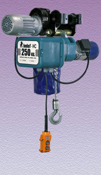
All Purpose Chain ELectric Hoist

Manufactured in ISO 9001:2008 certified company
Assured quality and interchangeability of parts
Rugged European design
Assured reliability
Overload slipping clutch
Safety assured
Compact aluminium alloy cast body
Light weight precision engineered
Anti corrosive powder coated finish
Better aesthetics
Imported grade 80 surface hardened load chain for strength & wear resistance
Longer chain life
Built in electrical control panel
Ready to use
Ergonomically designed pendent control
Easy of usage
Swiveling bottom block
Free rotation handling of loads
Precision machine cut case hardened alloy steel gears and load chain wheel
Long life, noiseless operation
Add on features:
- Remote control, VVVF drive, special lower blocks, PLC.
- Multiple hoist tandom automated operation.

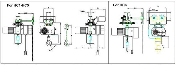
Specifications/Dimensions (mm)
| Chain size Diameter in mm |
FEM duty |
ISO duty |
Capacity in kg. |
Lifting speed mpm | No. of falls |
Motor kw main/creep |
Motor RPM |
'A' Headroom | B | C | G | H | L | Wt(kg) Hook susp. 3m lift |
Wt.kg; with ET 3m lift |
||||
| Single | Dual | HOOK SUSP |
PT | GT/ET | |||||||||||||||
| HC1 012NH | 4 | 125 | o | ONI | 0.25 | 1500 | 360 | 400 | 420 | 238 | 128 | 31 5 | 250 | 230 | 30 | 65 | |||
| HC1 012DH | 8/2.6 | ONE | 0.25/0.08 | 1500/410 | 360 | 400 | 420 | 31 5 | 250 | 230 | 35 | 70 | |||||||
| HC1 025NL | 1Am | M4 | 250 | 4 | ONI | 0.25 | 1500 | 360 | 400 | 420 | 31.5 | 250 | 230 | 30 | 65 | ||||
| HC1 025DL | 4/1.3 | ONE | 0.25/0.08 | 1500/410 | 360 | 4110 | 420 | 31.5 | 250 | 230 | 35 | 70 | |||||||
| HC2 025NH | 6 | 8 | ONE | 0.55 | 1500 | 440 | 460 | 460 | 31.5 | 350 | 280 | 40 | 75 | ||||||
| HC2 025DH | 8/2.6 | ONI. | 0 55/0 18 | 150U 410 | 440 | 460 | 460 | 31.5 | 350 | 280 | 44 | 79 | |||||||
| HC2 050NL | 1Am | M4 | 500 | 4 | ONE | 0.55 | 1500 | 440 | 460 | 460 | 31 5 | 0.15 | 280 | 40 | 75 | ||||
| HC2 050DL | 4/1.3 | ONE | 0 55/0.18 | 1500/410 | 440 | 460 | 460 | 31 5 | 350 | 280 | 44 | 79 | |||||||
| HC3 050NH | 7 | 8 | ONE | 9 | 1500 | 440 | 460 | 460 | 31.5 | 390 | 290 | 55 | 90 | ||||||
| HC3 050DH | 8/2 6 | ONE | 0.85/0.3 | 1500/460 | 550 | 560 | 560 | 31.5 | 390 | 290 | 60 | 95 | |||||||
| HC3 100NL | 1Am | M4 | 1000 | 4 | ONE | 9 | 1500 | 550 | 560 | 560 | n 5 | 390 | 290 | 55 | 90 | ||||
| HC3 100DL | 4/1.3 | ONE | 085/0.3 | 1500/460 | 550 | 560 | 560 | 31.5 | 390 | 290 | 60 | 95 | |||||||
| HC4 100NH | 10 | 8 | ONE | 1 84 | 1500 | 600 | 625 | 625 | 31 5 | 445 | 380 | 90 | |||||||
| HC4 100DH | 8/2.6 | ONE | 1.7/0.6 | 1500/460 | 600 | 625 | 625 | 31.5 | 445 | 380 | 94 | 129 | |||||||
| HC4 200NL | 1Am | M4 | 2000 | 4 | ONE | 1 84 | 1500 | 600 | 625 | 625 | 350 | 157 | 37.5 | 445 | 380 | 90 | 135 | ||
| HC4 200DL | 4/1.3 | ONE | 1 '/0.6 | 1500/460 | 600 | 625 | 625 | 37.5 | 4.15 | 380 | 94 | 139 | |||||||
| HC4 250NL | 1Am | M4 | 2500 | 4 | ONE | 2.2 | 1500 | 600 | 625 | 625 | 37.5 | 445 | 380 | 90 | 150 | ||||
| HC4 250DL | 4/1.3 | ONE | 2.5/0.8 | 1500/490 | 600 | 625 | 625 | 37.5 | 445 | 380 | 98 | 158 | |||||||
| HC5300NL | 1Am | M4 | 3000 | 4 | TWO | 35 | 1500 | 950 | 870 | 870 | 45.5 | 300 | 400 | 125 | 185 | ||||
| HC5 300DL | 4/1.3 | TWO | 3.5/1.2 | 1500/460 | 950 | 870 | 870 | 45.5 | 300 | 400 | 135 | 200 | |||||||
| HC6 500NL | 1Am | M4 | 5000 | 4 | TWO | 4.5 | 1500 | 1000 | NA | 1000 | 490 | 220 | 53 | 300 | 400 | 150 | 230 | ||
| HC6 500DL | 4/1.3 | TWO | .1 5 ' 5 | 1500/460 | 1000 | NA | 1000 | 53 | 300 | 400 | 160 | 250 | |||||||
NOTE :
* Key abbreviations used in models are :
H- High Hoisting speed(8 & above) N- Single speed (Normal speed)
L- Low Hoisting speed (4 & below) D- Dual speed
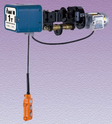
Travelling Trolly
 • Anti drop and de-railing guide
• Precision-machine runners mounted on sealed ball bearings
• Available in three basic range with further adjustment of flange width
• Anti corrosive powder coated finish
• Non standard speeds, dual speeds available on request
• Compatible to VVVF designs

Specifications/Dimensions (mm)
| Electric | |||||||
| Capacity | MT | 1 | 3 | ||||
| Inside of wheel flanges mm |
Range 1 | 58-150 | 90-160 | ||||
| Range 2 | 150-210 | 160-220 | |||||
| Range 3 | 210-305 | 220-305 | |||||
| A Seat of susp. plate to runner tread mm |
Range 1 & 2 | 89 | 110 | ||||
| Range 3 | 129 | 155 | |||||
| B Runner tread diameter | mm | 65 | 90 | ||||
| C Runner tread width | mm | 25 | 30 | ||||
| D Runner centres | mm | 128 | 157 | ||||
| E Underside of runner to suspension plate | 28 | 28 | |||||
| F Underside of runners to top of control panel mm |
120 | 120 | |||||
| G Beam flange to Panel end mm | 287 | 287 | |||||
| H Underside of runner to top of motor | 138 | 138 | |||||
| J Track centre line | Range 1 | track | 58-150 | 90-160 | |||
| and to motor | widths J | mm | 350-390 | 360-395 | |||
| Range 2 | track | 150-210 | 160-220 | ||||
| widths J | mm | 390-420 | 395-425 | ||||
| Range 3 | track | 210-305 | 220-305 | ||||
| widths J | mm | 420-470 | 425-470 | ||||
| K Depth of plate | Range 1,2&3 | mm | 21 | 34 | |||
| L Overall length | mm | 238 | 350 | ||||
| M Underside of runner to flange (push) mm | 75 | 105 | |||||
| N Underside of runner to gear tip (geared) mm | 90 | 115 | |||||
| Minimum radius of track curve mm | 2000 | 2500 | |||||
| Electric travel weight in kg |
Range 1 | 22 | 31 | ||||
| Range 2 | 23 | 33 | |||||
| Range 3 | 26 | 38 | |||||
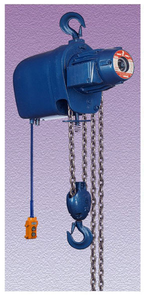
Medium duty Chain Electric Hoist - Model - BABY

Manufactured in ISO 9001:2008 certified company -
Assured quality & interchangeability of parts
Grade 80 load chain
Higher safety factor & longer chain life
Rugged German design in use for more than 30 years
Assured reliability
Precision machine case hardened alloy steel gears
Long life noiseless operation
Light weight simple mounting design
Ease of installation
Built in electrical control panel
Ready to use
Precision machine & hardened load chain wheel
Longer life of LCW & chain smooth operation

SPECIFICATIONS/DIMENSIONS (mm)
"BABY" with hook suspension (Fig.1) |
||||||||
| Capacity | MT | 0.5 | 1 | 2 | 0.5 | 1 | 2 | |
| Chain falls | No. | 2 | 2 | 4 | A | 750 | 750 | 860 |
| Hoisting speed | m/min | 4.8 | 4.8 | 2.4 | B | 150 | 150 | 150 |
| Hoist motor | H.R | 1.5 | 1.5 | 1.5 | C | 120 | 120 | 120 |
| *Height of max. lift (Std. 3 m) | m | 9.6 | 9.6 | 4.8 | 0 | 31 | 31 | 37 |
| Length of control cable | m | At your choice | E | 525 | 525 | 525 | ||
| Approx. wt. with chains for 3 m. lift | kg. | 63 | 63 | 65 | F | 285 | 285 | 285 |
| Approx. wt. per metre additional lift | kg. | 2.6 | 2.6 | 5.2 | ||||
* Higher lifts offered on request
"BABY" with electric trolley (Fig.2) |
||||||||
| Capacity | MT | 0.5 | 1 I | 2 | 0.5 | 1 | 2 | |
| Travelling speed | m/min. | 10 | 10 | 10 | A for C Max A for C Min. |
493 370 |
493 370 |
500 395 |
| Travelling motor | H.R | 0.25 | 0.25 | 0.25 | B C Max. C Min. |
840 305 58 |
840 305 58 |
965 305 90 |
| Min. runaway bend (radius of curvature) |
mm | 1500 | 2000 | 2500 | DMin. E F |
150 525 285 |
150 525 285 |
200 525 285 |
| G HMin. * J Max. |
31 23 28 |
31 23 28 |
37 14 28 |
|||||
| Approx. weight with chain for 3 mtr. lift | kgs. | 87 | 87 | 96 | ||||
| Approx. weight per metre additional lift. | kgs. | 2.6 | 2.6 | 5.2 | ||||
* To Calculate Clearance under beam subtract beam flange thickness from K
* Std supply will be with hook suspension
"BABY'' with Electric Trolley (Fig. 3) |
||||||||
| Capacily | MT | 0.5 | 1 | 2 | 0.5 | 1 | 2 | |
| Travelling Speed | m/min. | 10 | 10 | 10 | A for C Max A for C Min. |
493 370 |
493 370 |
500 395 |
| Travelling Motor | H.R | 0.5 | 0.5 | 0.5 | B CMax. |
840 305 |
840 305 |
965 305 |
| CMin. | 58 | 58 | 90 | |||||
| DMin. | 150 | 150 | 200 | |||||
| Min. runaway bend (radius of curvature) |
mm | 1500 | 1500 | 1500 | E F G HMin. *J Max. |
525 285 31 23 28 |
525 285 31 23 28 |
525 285 37 14 28 |
| Approx. weight with chain for 3 mtr. lift | Kgs. | 87 | 87 | 96 | ||||
| Approx. weight per metre additional lift. | Kgs. | 2.6 | 2.6 | 5.2 | ||||
* To calculate clearance under beam subtract beam flange thickness from J

