Electric Wire Rope Hoist
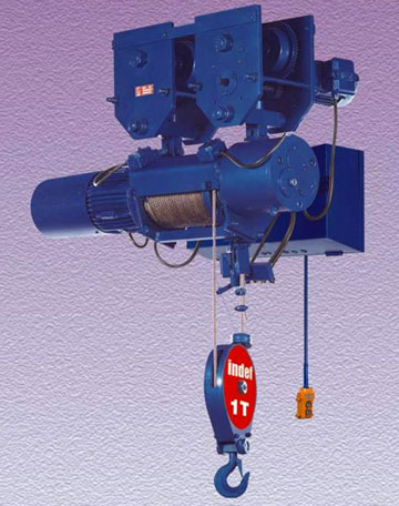
Heavy duty class IV robust design
Smooth operation even in toughest of application.
Manufactured in ISO 9001:2000 certified company
Assured quality and interchangeability of parts.
Truly modular constructor
Easily accessible separate brake, motor, drum, gear box & panel unit.
Seamless pipe accurately machined rope drum
Long life
Unique and sturdy rope guide arrangement
Prevents rope slackening and easy change of rope
Precision machine cut case-hardened alloy steel gears
Noiseless operation long life
Fail safe disc brake
Trouble free operation and ease of adjustment
Built in control panel with std. electricals
Ready to use.
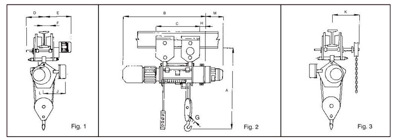
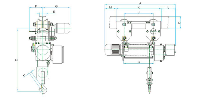
Specifications/Dimensions (mm)
| Type | WRH 1 | WRH II | WRH III | WRH 1 | WRH II | WRH III | WRH III * | |||||||||||||||
| Model | NP10I | NP201 | NP301 | NP102 | NP202 | NP302 | NP303 | |||||||||||||||
| Class | IV | IV | II | IV | IV | IV | II | IV | IV | II | ||||||||||||
| S.WL. (Tonne) | 1.0 | 2.0 | 2.5 | 3.0 | 2.0 | 4.0 | 5.0 | 6.0 | 7.5 | 10.0 | ||||||||||||
| Lift (Mtrs.) | 6 | 12 | 20 | 6.6 | 11.4 | 19.2 | 6.8 | 11.8 | 20 | 3 | 6 | 10 | 3.3 | 5.7 | 9.6 | 3.4 | 5.9 | 10 | 4 | 6 | ||
| Approx. Wt. (Kg.) | 264 | 286 | 322 | 386 | 414 | 459 | 533 | 546 | 568 | 296 | 318 | 354 | 4/8 | 497 | 563 | 638 | 818 | 828 | 900 | 1000 | ||
| Dim. B | 1075 | 1285 | 1555 | 1170 | 1340 | 1610 | 1255 | 1425 | 1695 | 1075 | 1285 | 1555 | 1170 | 1340 | 1610 | 1255 | 1425 | 1695 | 1425 | 1695 | ||
| Dim. C | 552 | 752 | 1022 | 588 | 758 | 1028 | 635 | 805 | 1075 | 552 | 752 | 1022 | 635 | 805 | 1075 | 635 | 805 | 1075 | 1050 | 1295 | ||
| Hoisting Speed m/min |
9 | 8 | 8 | 4.5 | 4 | 4 | 2.66 | |||||||||||||||
| Hoisting Motor H.R IK.W.) |
3(2.2) | 5(3.7) | 7.5 15.51 | 3(2.2) | 5(3.7) | 7.5 (5.5) | 7.5 (5.5) | |||||||||||||||
| Travelling Speed * m/min |
17 | 17 | 17 | 17 | 17 | 17 | 17 | |||||||||||||||
| Travelling Moto» HP [K.W.) |
0.25 [0.18) | 0.25 (0.18) | 0.5 (0.37) | 0.25 (0.18) | 0.5 (0.37) | 0.75 (0.55) | 0.75 (0.55) (2 nos.) |
|||||||||||||||
| Min. Height of 'I' beam (mm) |
" 175 | " 175 | 250 | " 175 | 250 | 250 | 300 | |||||||||||||||
| F Min. - Max. | 90 - 180 | 90-180 | 125-210 | 90- 180 | 125 - 210 | 125-210 | ||||||||||||||||
| A Headroom | 1170 | 1370 | 1480 | 1110 | 1345 | 1460 | 1825 | |||||||||||||||
| D Min. - Max. * | 151 - 196 | 151 - 196 | 163 - 178 | 151 ■ 196 | 163 - 1/8 | 163 - 1/8 | 452 - 48/ | |||||||||||||||
| E Min. - Max. | 399 ■ 444 | 399 - 444 | 412-457 | 399 444 | 412-457 | 412-457 | 452 - 487 | |||||||||||||||
| G | 31 | 3/ 42 | 42 | 37 | 51 | 67 | 89 | |||||||||||||||
| H | 130 | 1-13 | M0 | 130 | 120 | 140 | 371 | |||||||||||||||
| 1 | 230 | 290 | 330 | 320 | 405 | 480 | 371 | |||||||||||||||
| J | 270 | 315 | 365 | 305 | 350 | 395 | 625 | |||||||||||||||
| K | 305 | 305 | 495 | |||||||||||||||||||
| M + | 380 | 380 | 380 | |||||||||||||||||||
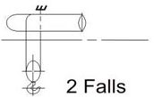
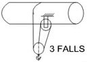
| No. of falls construction |
 |
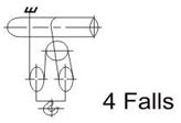 |
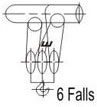 |
|||||||||||||||||||
NOTE :
* Key abbreviations used in models are :
H- High Hoisting speed(8 & above) N- Single speed (Normal speed)
L- Low Hoisting speed (4 & below) D- Dual speed
* All Dimensions in mm. Data is subjected to change without prior notice
Medium Duty WRH
Medium Duty WRH NO/N
SPECIFICATIONS/DIMENSIONS (mm)
| WRH NO | WRH N | |||||||||||||||||
| Capacity (SWL) | MT | 0.5 | 1 | 2 | 3 | |||||||||||||
| Lift | Mtrs. | 3.5 | 6 | 9 | 12 | 3.5 | 6 | 9 | 12 | 5.2 | 8.2 | 1 12 | 3.4 | 5.4 | 7.4 | |||
| A | mm | 867 | 974 | 1103 | 1232 | 867 | 974 | 1103 | 1232 | 990 | 1119 | 1248 | 990 | 1119 | 1248 | |||
| B | mm | 316 | 423 | 552 | 681 | 316 | 423 | 552 | 681 | 385 | 514 | 643 | 385 | 514 | 643 | |||
| Approx. Weight | Kg | 114 | 160 | 170 | 175 | 119 | 164 | 175 | 180 | 225 | 240 | 255 | 300 | 315 | 330 | |||
| No. of Falls |
|
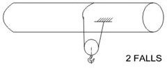 |
 |
|||||||||||||||
| Hoist speed | MPM | 5 | 5 | 5 | 3.3 | |||||||||||||
| Trolley speed | MPM | 15 | 15 | 15 | 15 | |||||||||||||
| Hoist motor | HP | 1.5 (1.11 KW) | 1.5(1.11 KW) | 3 (2.2 KW) | 3 (2.2 KW) | |||||||||||||
| Trolley motor | HP | 0.25 (0.18 KW) | 0.25 (0.18 KW) | 0.25 (0.18 KW) | 0.5 (0.37 KW) | |||||||||||||
| C | Head room | mm | 790 | 880 | 1070 | 1315 | ||||||||||||
| D | Min. beam height | mm | 175 | 175 | 175 | 175 | ||||||||||||
E |
Min. flange | mm | 90 | 90 | 90 | 90 | ||||||||||||
| Max. flange | mm | 210 | 210 | 210 | 210 | |||||||||||||
F |
for min. flange | mm | 189 | 189 | 189=G ' | 189=G ' | ||||||||||||
| for min. flange | mm | 169 | 169 | 169=G' | 169=G ' | |||||||||||||
| G | for max. flange | mm | 381 | 381 | 381 | 381 | ||||||||||||
| for max. flange | mm | 441 | 441 | 441 | 441 | |||||||||||||
| H | mm | 31.5 | 31.5 | 34 | 42 | |||||||||||||
| J | mm | 300 | 407 | 536 | 665 | 300 | 407 | 536 | 665 | 369 | 498 | 627 | 369 | 498 | 627 | |||
| K | mm | 524 | 631 | 760 | 889 | 524 | 631 | 760 | 889 | 593 | 722 | 851 | 593 | 722 | 851 | |||
| L | mm | 187 | 187 | 197 | 197 | |||||||||||||
| M | mm | 156 | 156 | 200 | 200 | |||||||||||||
| C | Head room (with O.L.D.) | mm | 890 | 980 | 1070 | - | ||||||||||||
| Data tolerance ± 10% | ||||||||||||||||||
Medium duty WRH NO-HL/N-HL
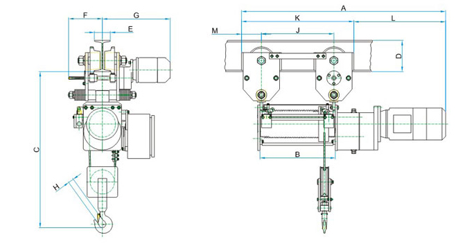
SPECIFICATIONS/DIMENSIONS (mm)
| WRH NO-HL | WRH N-HL | |||||||||||||||||
| Capacity (SWL) | MT | 0.5 | 1 | 2 | 3 | |||||||||||||
| Lift | Mtrs | 18 | 25 | 18 | 25 | 17.2 | 25 | 11.4 | 16.5 | |||||||||
| A | mm | 1662 | 1964 | 1662 | 1964 | 1626 | 1964 | 1626 | 1964 | |||||||||
| B | mm | 939 | 1241 | 939 | 1241 | 903 | 1241 | 903 | 1241 | |||||||||
| Approx. weight | Kg | 18f> | 215 | 190 | 220 | 285 | 315 | 360 | 390 | |||||||||
|
No. of falls |
|
|
|
||||||||||||||
| Hoist speed | MPM | 5 | 5 | 5 | 3.3 | |||||||||||||
| Trolley speed | MPM | 15 | 15 | 15 | 15 | |||||||||||||
| Hoist motor | HP | 1.5(1.11 KW) | 1.5(1.11 KW) | 3 (2.2 KW) | 3 (2.2 KW) | |||||||||||||
| Trolley motor | HP | 0.25 (0.18 KW) | 0.25 (0.18 KW) | 0.25 (0.18 KW) | 0.5 (0.37 KW) | |||||||||||||
| C | Head room | mm | 790 | 880 | 1070 | 1315 | ||||||||||||
| D | Min. beam height | mm | 175 | 175 | 175 | 175 | ||||||||||||
| E | Min. Flange | mm | 90 | 90 | 90 | 90 | ||||||||||||
| Max. flange | mm | 210 | 210 | 210 | 210 | |||||||||||||
| F | for min. flnage | mm | 189 | 189 | 189=G * | 189=G ' | ||||||||||||
| for max. flange | mm | 169 | 169 | 169=G* | 169=G* | |||||||||||||
| G | for min. flange | mm | 381 | 381 | 381 | 381 | ||||||||||||
| for max. flange | mm | 441 | 441 | 441 | 441 | |||||||||||||
| H | mm | 31.5 | 31.5 | 34 | 42 | |||||||||||||
| J | mm | 923 | 1225 | 1442 | 1659 | 923 | 1225 | 1442 | 1659 | 887 | 1225 | 1442 1659 | 887 | 1225 | 1442 | 1658 | ||
| K | mm | 1147 | 1449 | 1666 | 1883 | 1147 | 1449 | 1666 | 1883 | 1111 | 1449 | 1666 1883 | 1111 | 1449 | 1666 | 1882 | ||
| L | mm | 515 | 515 | 515 | 515 | |||||||||||||
| M | mm | 112 | 112 | 112 | 112 | |||||||||||||
| C | Head room (with OLD.) | mm | 890 | 980 | 1070 | - | ||||||||||||